![]()
![]()
![]()
![]()
![]()
![]()
![]()
![]()
![]()
![]()
![]()
![]()
![]()
![]()
![]()
![]()
![]()
![]()
![]()
![]()
![]()
![]()
Creating the The Lotus 72C in
1:12 Scale
Page 3
Updated
4/5/08
March 25th. 2008:
New page format as well. Lets see how it
works out. I have made a couple of attempts at producing the Aluminum tub and
made some discoveries along the way, hence more than one attempt. ;) It will
be multiple sections all photo etched, with all marks for folding and rivets;
you will have the option of drilling the marks and installing the supplied
rivets, or you will be able to take a scriber on the back side and push down
to produce the rivet head as can be seen in the pictures here.
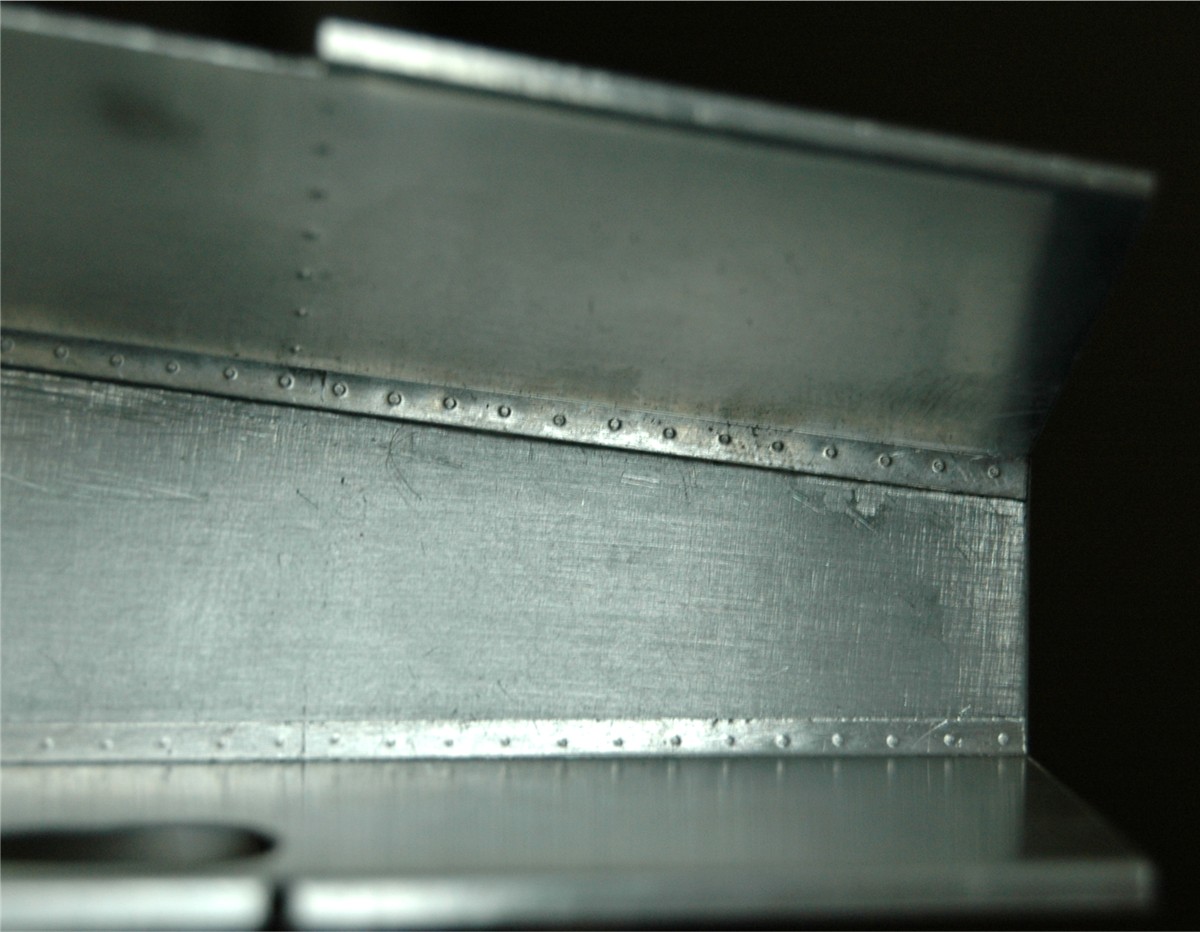

There is still quite a bit to do here. You
can just see the edge of the seat just below the Gear shift pocket, in the 3rd
picture. The final parts will be slightly different to what you see here, but
not by much.
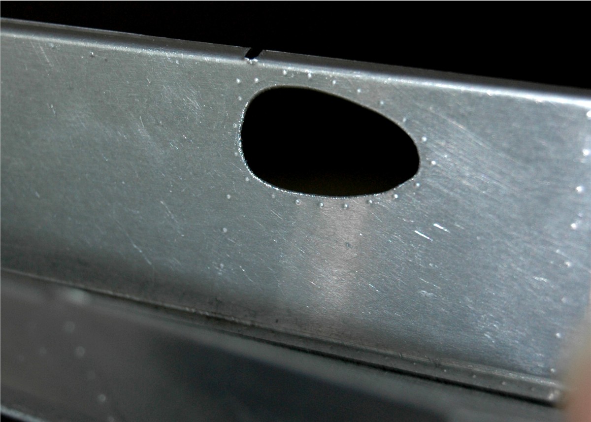
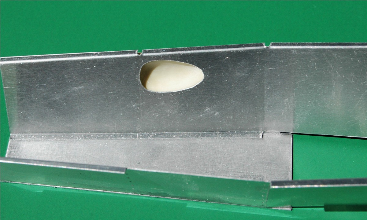
For the gear shift
indent/pocket, I took a piece of brass wire gauze/fabric/mesh (whatever you
want to call it) and pushed it through the hole in the tub from the inside,
until I achieved the shape I wanted. I then poured a little resin in it (to
make the shape permanent). Once it
cured I smoothed it out
 then trimmed the mesh and checked the fit
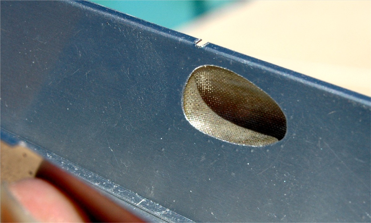
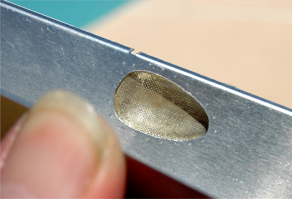 as you can see, it's not too bad. From that piece I will be able to make a
mold and then cast it in either white metal or resin.
as you can see, it's not too bad. From that piece I will be able to make a
mold and then cast it in either white metal or resin.
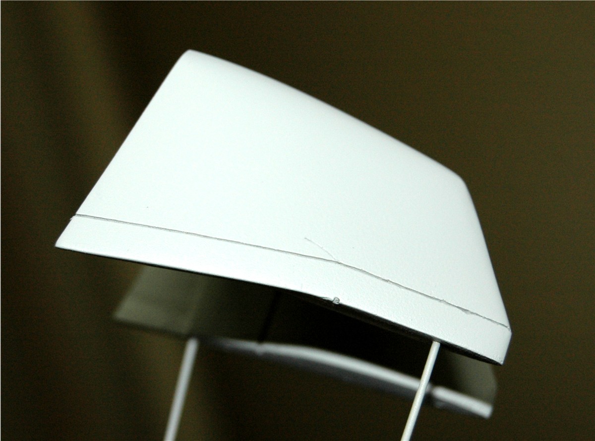
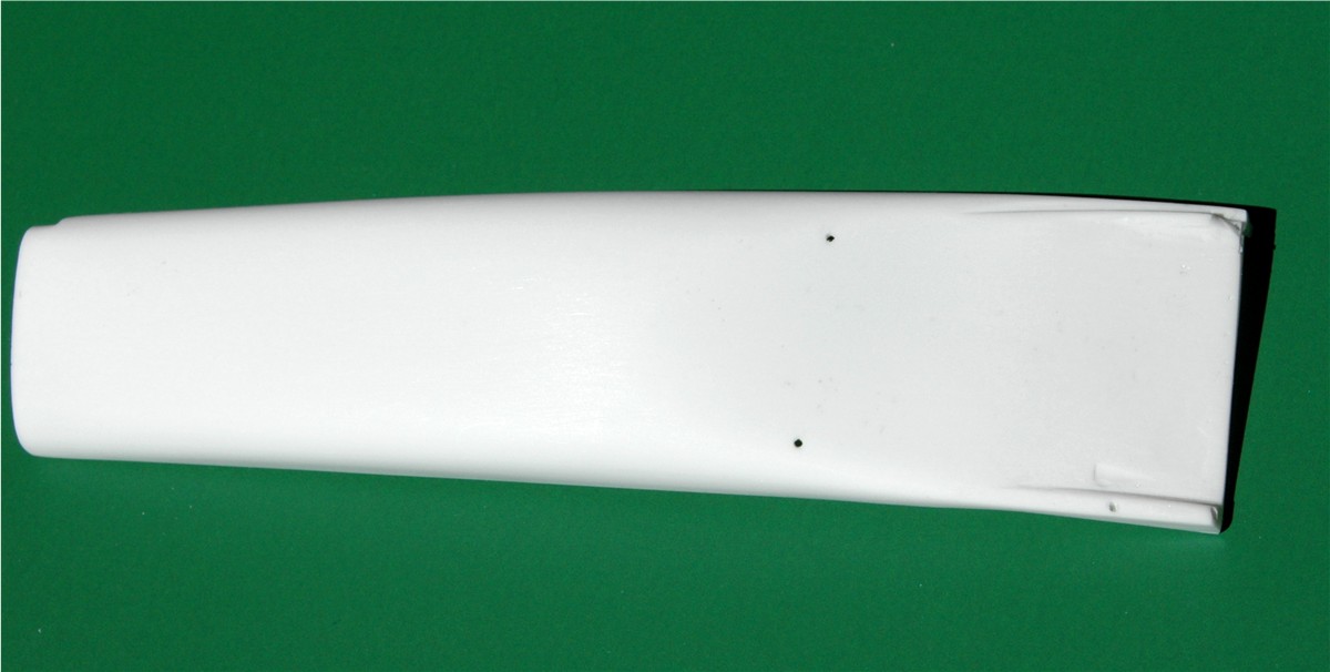
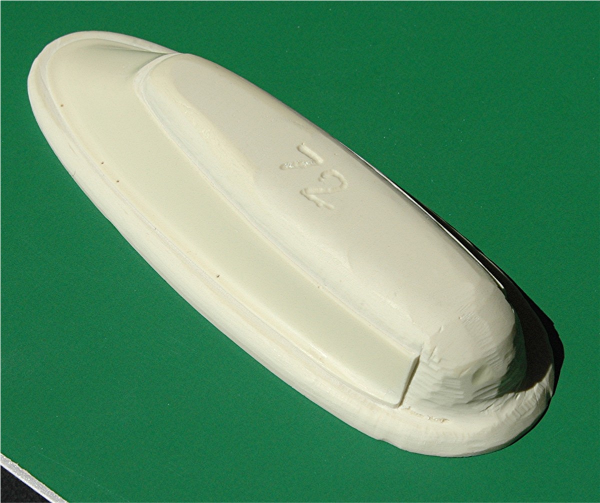
The side pods have
caused me some concern to make them correctly, without having any decent
drawings of them, however, with the aide of the Radiator drawings an one good
reference picture (which unfortunately I cannot share with you) I was able to
do it. Thanks to Erich again, for that picture. This is the final version, ready to make the master from.
Top view
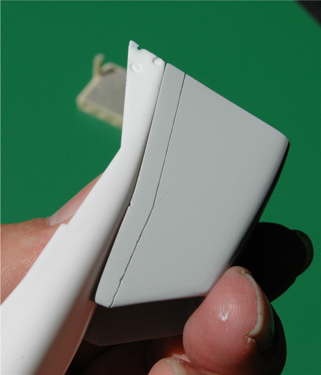
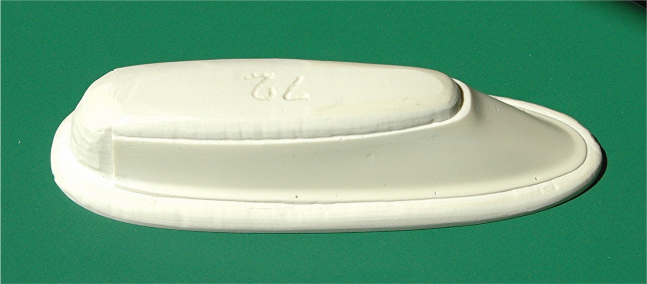
 Bottom view
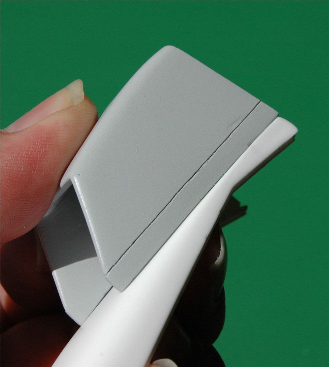
 As you can see I have scribed in the panel lines for the 2" larger side pods,
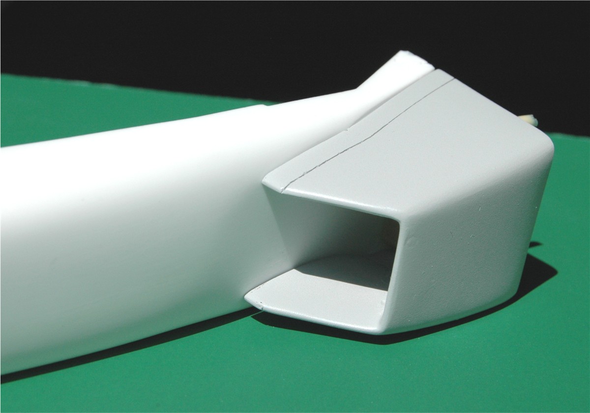
which were most commonly used through the season. Here you can see the inside
of the side pods.
As you can see I have scribed in the panel lines for the 2" larger side pods,
which were most commonly used through the season. Here you can see the inside
of the side pods.
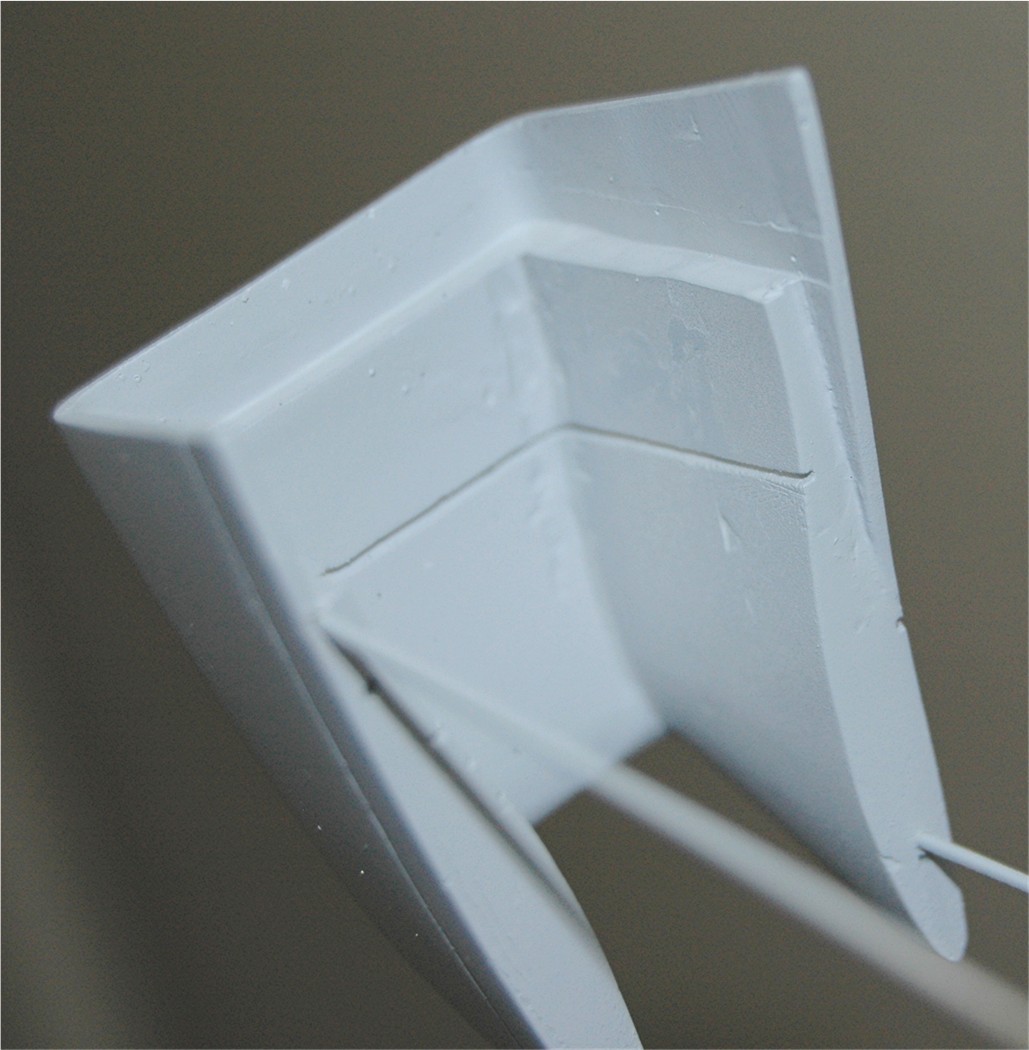
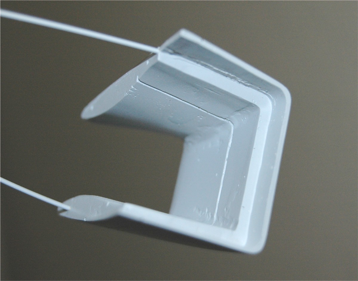 The radiators will butt up against the edge you can see there. The groove, a
little forward from the radiator, is for the wire screen to catch the garbage.
The radiators will butt up against the edge you can see there. The groove, a
little forward from the radiator, is for the wire screen to catch the garbage.
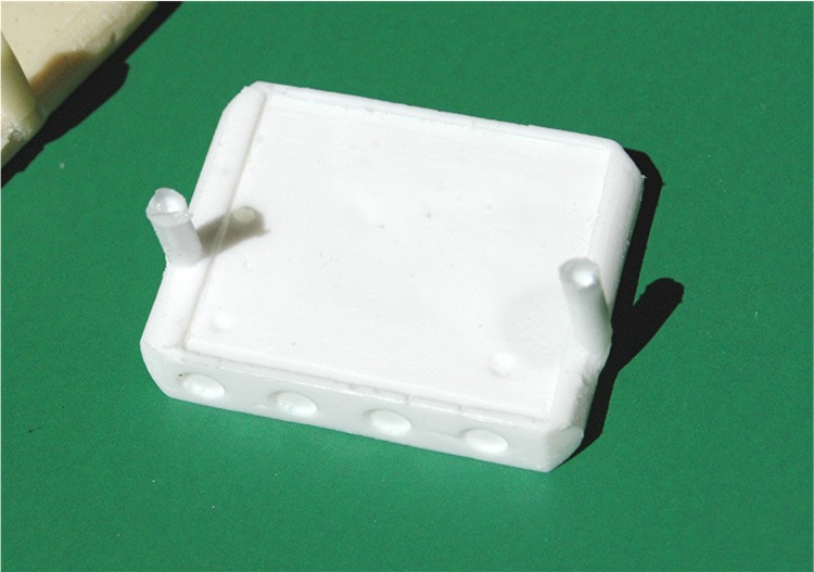
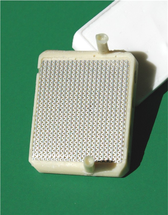
There were 4 different
radiator sizes used through the season. They were all the same height, 14.5"
and the same depth, 6 rows. They only varied in width. I chose to go with the
10.75" wide radiators, which seems to have been most commonly used through the
season. The widest being 11.5" and the narrowest being 8.75". At the moment I
have the radiator almost ready to cast for a master. You can see the water
pipes top and bottom, which need a little clean up before casting. The recess
in the face is there to accept a photo etch screen to give the radiator
detail.
 .
I did not need to, but I put the 4 holes in each side as well
.
I did not need to, but I put the 4 holes in each side as well
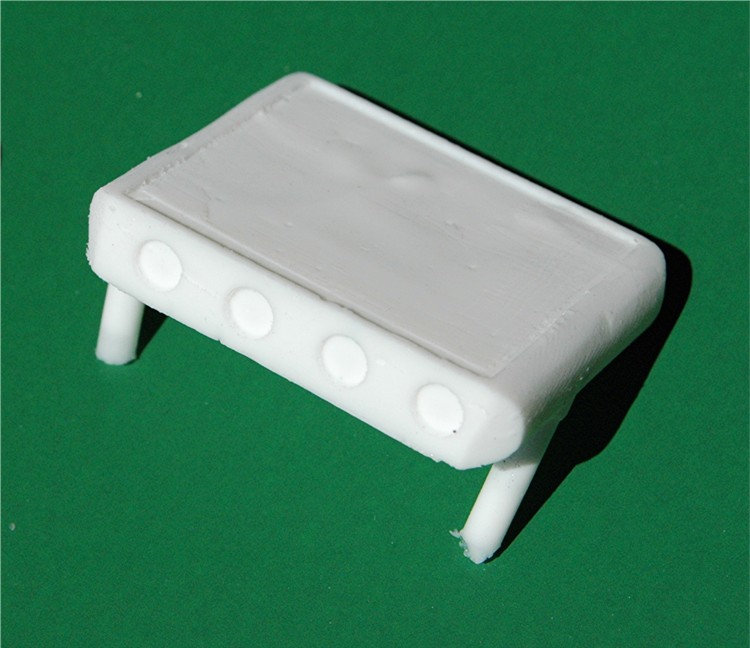
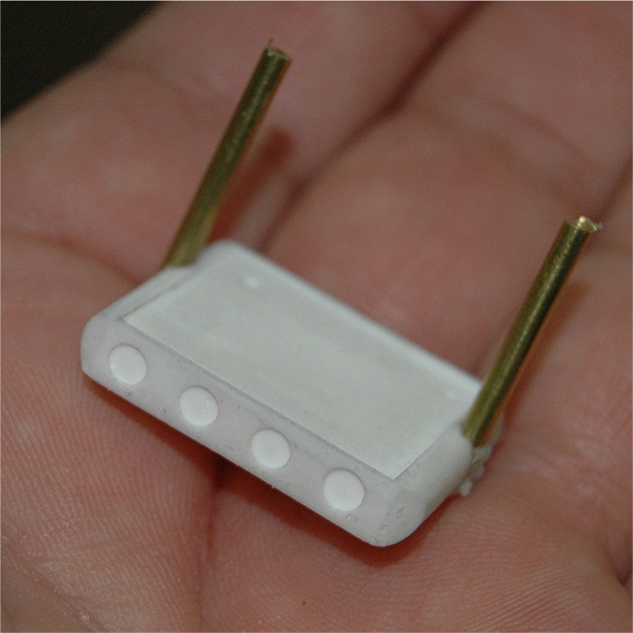 They are actually in the aluminum frame of the real radiators and being a bit
of a stickler for detail...........I put them in, although they will be hidden
in a fully assembled model. One other reason for detail like this is, some
modelers like to build dioramas and have parts off the car. You will be able
to do this with this kit. With the side pod removed, the radiators will still
be mounted to the body.
They are actually in the aluminum frame of the real radiators and being a bit
of a stickler for detail...........I put them in, although they will be hidden
in a fully assembled model. One other reason for detail like this is, some
modelers like to build dioramas and have parts off the car. You will be able
to do this with this kit. With the side pod removed, the radiators will still
be mounted to the body.
The 72C actually had 5 fuel tanks in it. I will be including resin versions of the four in the sides of the car, for anyone that wants to install them. There will of course be the main one behind the driver.
March 28th. 2008:
Just a short update with pictures to show how the bodywork is progressing,
this is the left side
 the holes are the temporary locating holes for the pins in the side pod.
 Side pod fits pretty well top and bottom
 I am happy with it so far.
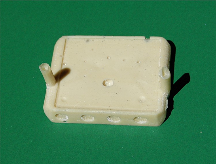
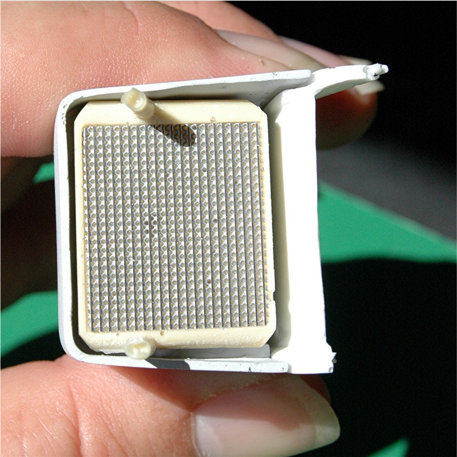
I have been having a
little trouble with producing the radiators with consistent quality. I am
going to have to mold them in a different way. As you can see, with the brown
resin I have a lot of air bubbles, which is due to the rapid cure time of that
resin. The white resin cures more slowly and therefore flows better, but still
has it's problems with the mold I made.
 .
To give you a better idea of how the radiators will look, I have added a piece
of photo etch.
.
To give you a better idea of how the radiators will look, I have added a piece
of photo etch.
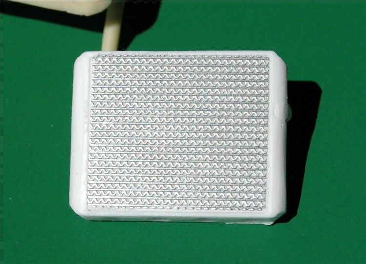
 It actually covers up most of the air bubbles, which if I cannot improve that,
is the worst that it could be, so if that is the worst part, I won't mind too
much. Roughly how they will look installed
It actually covers up most of the air bubbles, which if I cannot improve that,
is the worst that it could be, so if that is the worst part, I won't mind too
much. Roughly how they will look installed
 I wanted to make sure items fit as I proceed. I would hate to get too far into
the project and find I have to change it all (Again!)
I wanted to make sure items fit as I proceed. I would hate to get too far into
the project and find I have to change it all (Again!)
I have made the master
for the Gear shift recess.
 It is now ready to make a mold from it so I can try casting it in white metal.
I am very happy with the fit.
It is now ready to make a mold from it so I can try casting it in white metal.
I am very happy with the fit.
 I think it has just the right amount of recess.
While this is going on I have also been working on the engine, which I'm hoping I will have completed by the end of next week. Unfortunately I ran out of mold material and had to order more. So I have to work on different parts in the meantime.
March 29th. 2008:
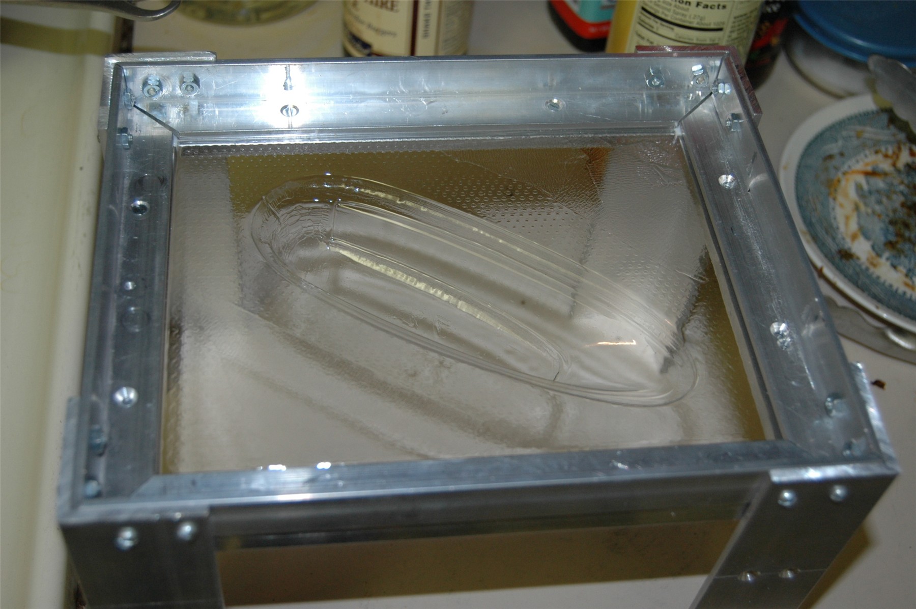
I went back to work on the buck for the windscreen. It has come a long way
since I first tried it. :) I learned a lot since this
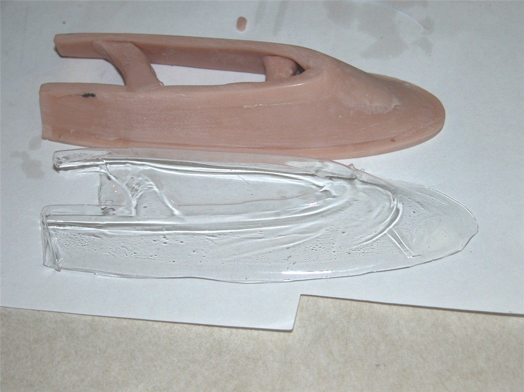 The new one is a solid chunk of resin.
 I have trimmed the shape so it will be easy to cut out from the Vacuum Formed
bubble. I did find some Yellow clear plastic, that I will test, as it is very
thin. If no good I will just go with clear and you will have to paint it clear
yellow.
I have trimmed the shape so it will be easy to cut out from the Vacuum Formed
bubble. I did find some Yellow clear plastic, that I will test, as it is very
thin. If no good I will just go with clear and you will have to paint it clear
yellow.

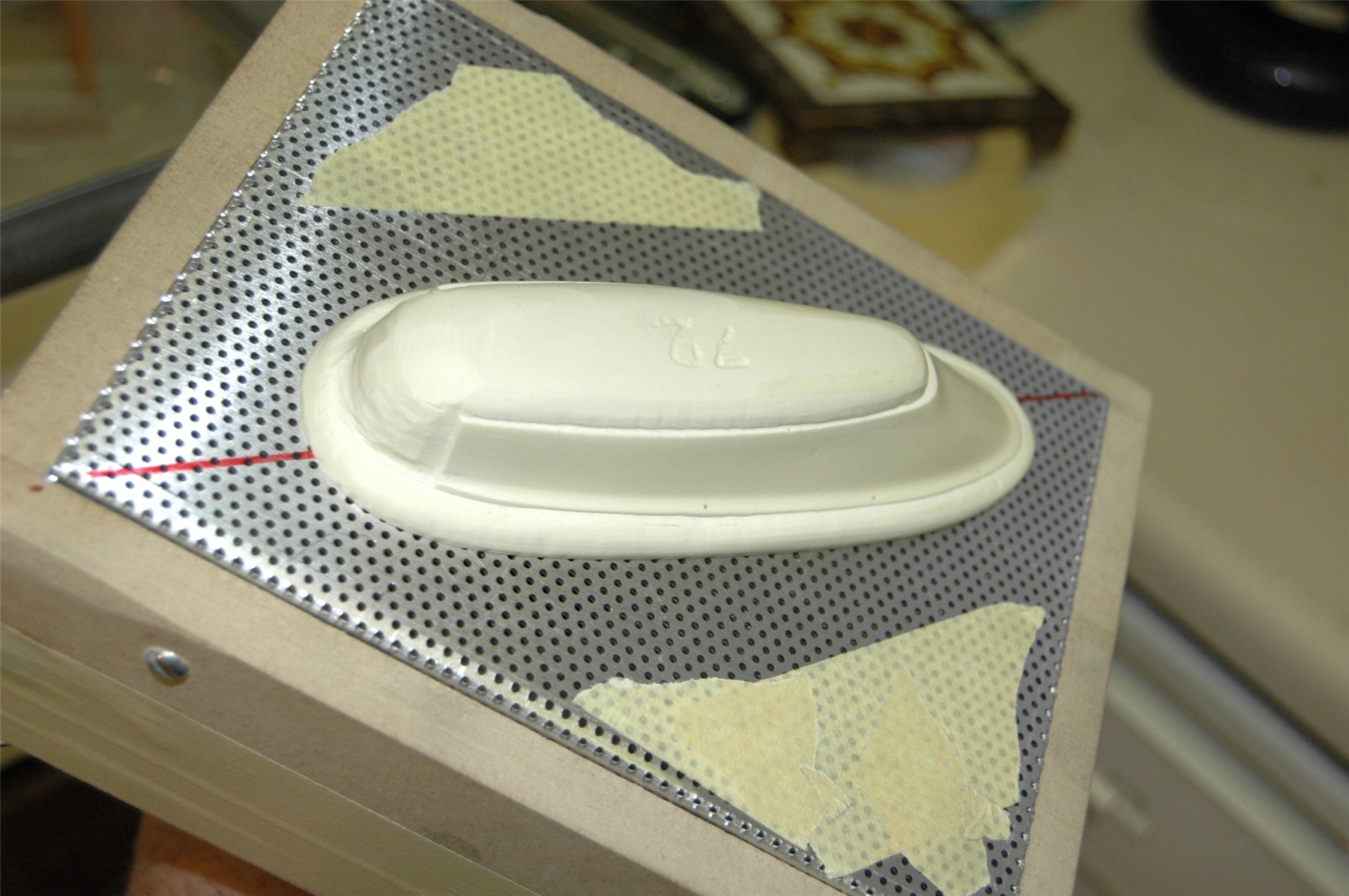
I have pointed out a couple of small problems. One being a stupid mistake
where I drilled one of the mounting holes too near the front. (The idea is
that when the windscreen is formed it will have a tiny dimple just where the
mounting hole/pin will go and make it easy to drill in the correct place.)
I will have to fill the hole in, along with a tiny bubble hole in the resin.
The thing with the buck is, any blemish will show up when Vacuum formed, so I
have to make sure the surface for the windscreen is really smooth. There are
two more mounting holes to go on each side, but until I produce one windscreen
I cannot locate them as they are on the head restraint section of the
bodywork.
 There
are a couple of small blemishes I need to get rid of on this side as well. I
have also become pretty good at sculpting now, as you can see. ;) (My Great
Grandfather's skills finally rubbing off on me "Pittenedrigh
MacGillivray") Not quite the same, but.............. :)
There
are a couple of small blemishes I need to get rid of on this side as well. I
have also become pretty good at sculpting now, as you can see. ;) (My Great
Grandfather's skills finally rubbing off on me "Pittenedrigh
MacGillivray") Not quite the same, but.............. :)
I have to finish off my vacuum forming box now, so I can test it and see how the windscreen comes out. I also re-thought the way to manufacture the radiators last night, so there will be a re-make on those.
Well I have started to
learn about white metal casting, it is not going to be easy, and I now
understand some of the problems that can be encountered.
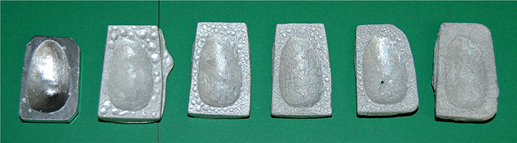
From left to right, in order of pour, all within 10 minutes of the first one.
All cast with the same mold and same pot of white metal. You can see how it
degrades so quickly. This was a big surprise! :(
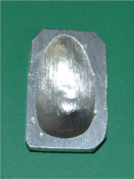
The first one was the
best so I worked on it to make it look like aluminum,
 that was a lot of work as you can see the kind of finish achieved by the
second and third pours. Not smooth at all, I was very surprised when I tipped
them out of the mold. I will have to read up on white metal casting. I am
going to try a different alloy tomorrow. I am going to have to get this right
as there will be so many white metal parts.
that was a lot of work as you can see the kind of finish achieved by the
second and third pours. Not smooth at all, I was very surprised when I tipped
them out of the mold. I will have to read up on white metal casting. I am
going to try a different alloy tomorrow. I am going to have to get this right
as there will be so many white metal parts.
I have done some research (If all else fails read
instructions) and found that I should have used some fine talcum powder in the
mold to allow the air to escape. I will do some more tests later.
April 5th. 2008:
In the last few days I have finished off my Vacuum Form box, so I could test
it on the windscreen. I tried 3 times in my "Hi-Tech" vacuum booth. You may
recognize the booth from my "spray booth" ;)
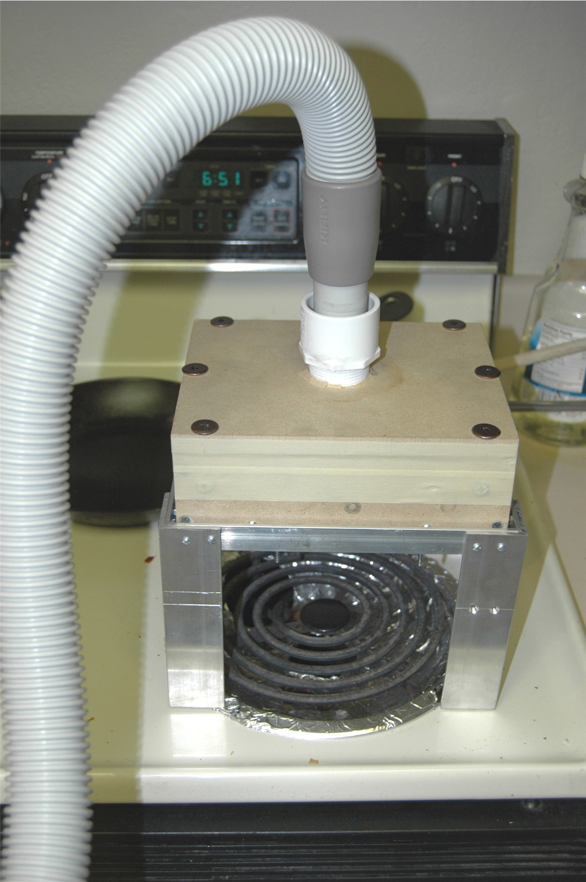 The system works pretty well actually
 but I think I need more suction. It's not sucking down tight enough at the
base of the windscreen, but this was only the 3rd attempt. Also I cannot find
my yellow tinted plastic to test so I have to get more. But I tell you after
testing this clear, I think it is too thin, a real pain to finish off.
but I think I need more suction. It's not sucking down tight enough at the
base of the windscreen, but this was only the 3rd attempt. Also I cannot find
my yellow tinted plastic to test so I have to get more. But I tell you after
testing this clear, I think it is too thin, a real pain to finish off.

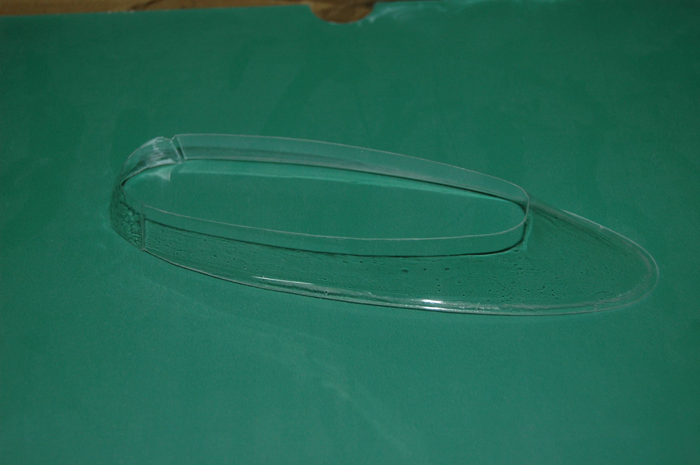 I had a lot of problem with dust to start with, but I think more suction is
the answer really. Hard to photograph as well. Anyway it must be the first
attempt at the correct windscreen. :) So I may have "Chevron" in Japan produce
them for me, I just need to send a "buck" to them.
I had a lot of problem with dust to start with, but I think more suction is
the answer really. Hard to photograph as well. Anyway it must be the first
attempt at the correct windscreen. :) So I may have "Chevron" in Japan produce
them for me, I just need to send a "buck" to them.
I have also re-worked
the axles, universal joints and drive shafts, they now look more accurate and
are more to scale than before, all in aluminum this time, but we shall see
what happens in the end. All these parts are prototype, not production.
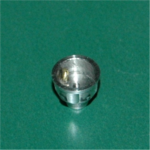
 This is the Axle and UJ body assembled as before with a screw inside the axle.
Again I have used the same drive principal with a small pin inside the UJ body
and a notch in the drive shaft. I also managed to produce a rubber boot for
the UJ. You can see it on the UJ cover with the drive shaft going through it,
This is the Axle and UJ body assembled as before with a screw inside the axle.
Again I have used the same drive principal with a small pin inside the UJ body
and a notch in the drive shaft. I also managed to produce a rubber boot for
the UJ. You can see it on the UJ cover with the drive shaft going through it,
 Here it is all broken down and just for a reference photo,
.jpg)
That's it for today.
If you want to see all the pictures of the whole process, click
here.
To
be continued................