![]()
![]()
![]()
![]()
![]()
![]()
![]()
![]()
![]()
![]()
![]()
![]()
![]()
![]()
![]()
![]()
![]()
![]()
![]()
![]()
![]()
![]()
![]()

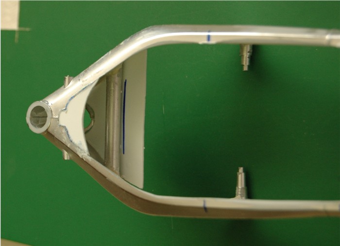
I have been playing with the frame and working on the fuel tank and air-box the last few days.
The frame has most all brackets in the wrong
place, and where the frame meets the steering head is wrong. So
this is what I started with
 I'm going to remove the foot rest brackets, the fairing brackets front and
side, its also too thick so I will need to thin it. I was going to make a new
frame altogether, but decided it would be easier to modify the kit one. I
decided to fill the frame with resin rather than skin the inside with plastic
sheet, because of the amount of thinning needed and the resin would help give
it strength.
I'm going to remove the foot rest brackets, the fairing brackets front and
side, its also too thick so I will need to thin it. I was going to make a new
frame altogether, but decided it would be easier to modify the kit one. I
decided to fill the frame with resin rather than skin the inside with plastic
sheet, because of the amount of thinning needed and the resin would help give
it strength.
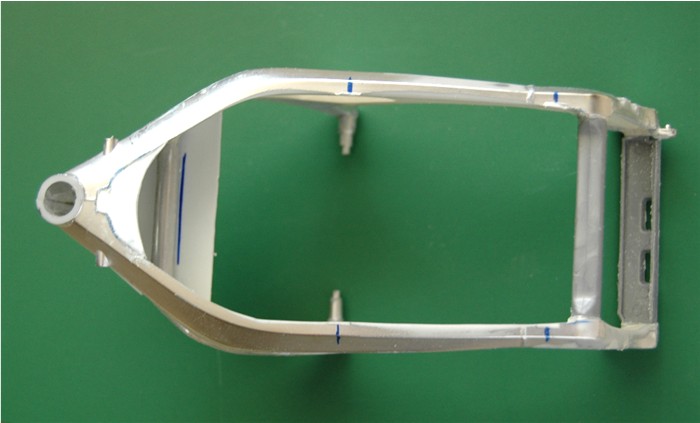
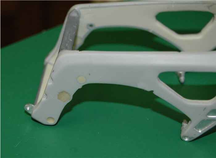
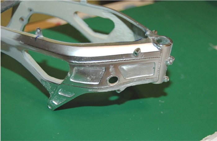 In the first picture, if you look carefully I have modified the frame where it
joins the steering head. I had to cut the bottom of the frame and "pinch" the
side of the frame in slightly. You can see the difference with the second
picture which has not been modified yet.
In the first picture, if you look carefully I have modified the frame where it
joins the steering head. I had to cut the bottom of the frame and "pinch" the
side of the frame in slightly. You can see the difference with the second
picture which has not been modified yet.
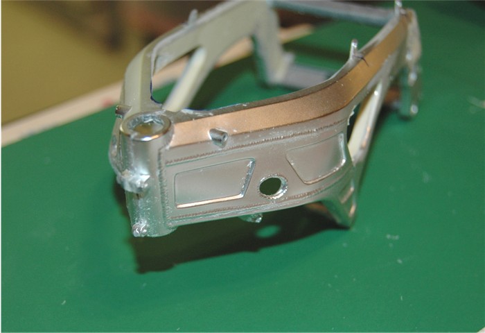 In the next two pictures you can see before
 and after
 thinning of the sides. I actually made a mistake and took too much out at the
steering head, I will rectify that in the next stage. I need to pinch in the
side of the frame that was not done, so I decided and easier way than the last
time. I removed the bottom lip of the frame completely, as I needed to make a
new skin for that part of the frame anyway. I also wanted to install a piece
of aluminum tube between the frame at the front, where the weld mark are
around the holes.
thinning of the sides. I actually made a mistake and took too much out at the
steering head, I will rectify that in the next stage. I need to pinch in the
side of the frame that was not done, so I decided and easier way than the last
time. I removed the bottom lip of the frame completely, as I needed to make a
new skin for that part of the frame anyway. I also wanted to install a piece
of aluminum tube between the frame at the front, where the weld mark are
around the holes.
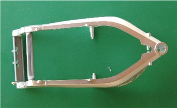
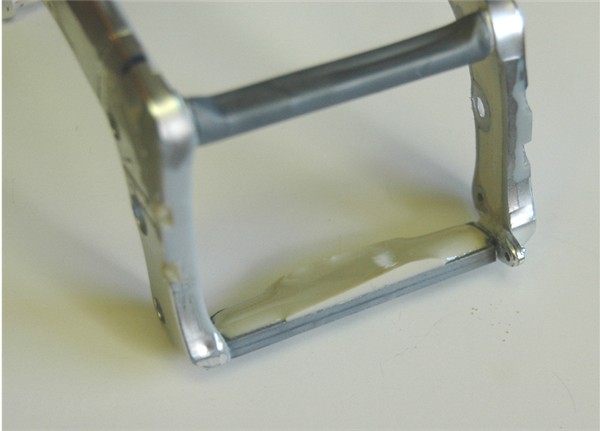
 Here you can see the tube installed and the new skin pieces, top and bottom. I
have also removed the remaining brackets on top of the frame, marking their
centers with blue marker, so I know where to install the new ones later
Here you can see the tube installed and the new skin pieces, top and bottom. I
have also removed the remaining brackets on top of the frame, marking their
centers with blue marker, so I know where to install the new ones later
 I do have to trim the top skin piece I inserted, but the glue needs to cure.
In this picture you can see the bottom skin
I do have to trim the top skin piece I inserted, but the glue needs to cure.
In this picture you can see the bottom skin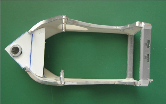 I cut it out larger so it would make my life easy modifying the frame and
hooked it over the steering head which allowed me to temporarily glue it at
the head so it would not flick up when I bent it down into the frame. When it
cures I will trim it to shape and remove the excess, ready for the inner skin.
I cut it out larger so it would make my life easy modifying the frame and
hooked it over the steering head which allowed me to temporarily glue it at
the head so it would not flick up when I bent it down into the frame. When it
cures I will trim it to shape and remove the excess, ready for the inner skin.
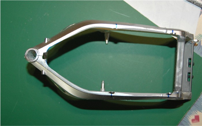
With the bottom skin in place I could pinch in the side of the frame and tack
it in place with super glue. I did not quite get it right
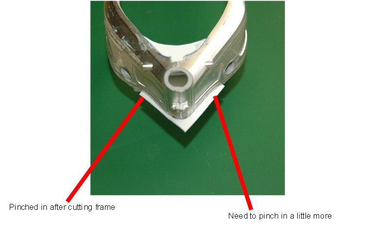 as you can see, but it will not be hard to adjust it later.
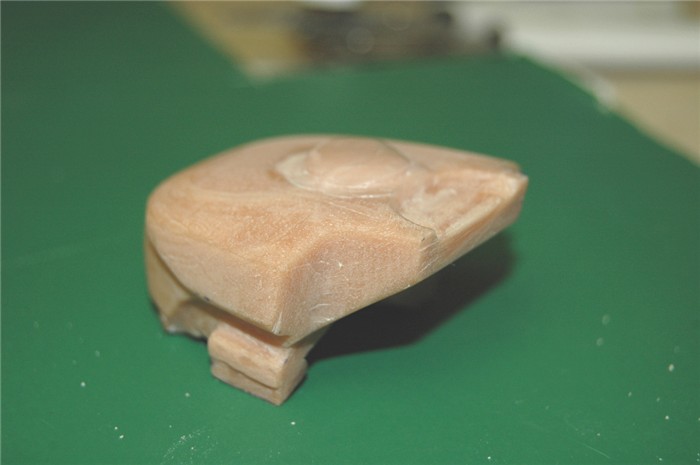
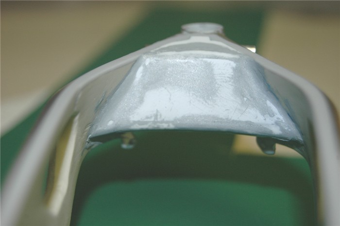
Put that to one side and continue with the fuel
tank and air-box. I used some sculpey and pressed it into the inside of the
die-cast tank cover so it filled it completely, trimmed the front and mounted
it on the seat support and frame, with slight pressure to give an indent so I
would know where to trim after it has cured. Put that in the oven at 275
degrees F for approx 1hr 15minutes. (I did that some days ago) This is what I
have after minimal clean up.

 It is hard to see the contours in these pictures. The front half will be the
air-box and obviously the back half will be the top part of the fuel tank. So
today I cut them apart and worked on the fuel tank, giving it the final
shaping
It is hard to see the contours in these pictures. The front half will be the
air-box and obviously the back half will be the top part of the fuel tank. So
today I cut them apart and worked on the fuel tank, giving it the final
shaping
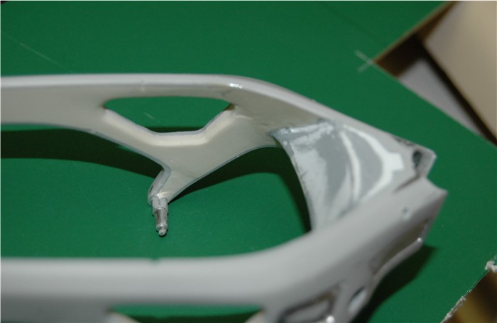
 before attaching it to the bottom half of the tank, so I can then make a mold.
I tried this once before and got it all wrong during the carving. I'm much
happier with it this time
before attaching it to the bottom half of the tank, so I can then make a mold.
I tried this once before and got it all wrong during the carving. I'm much
happier with it this time
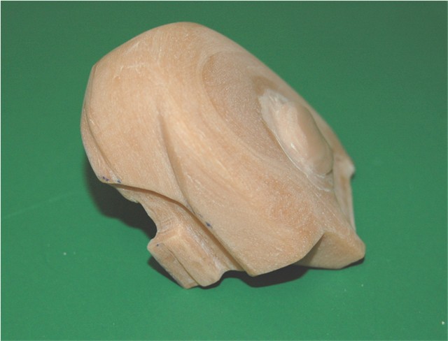
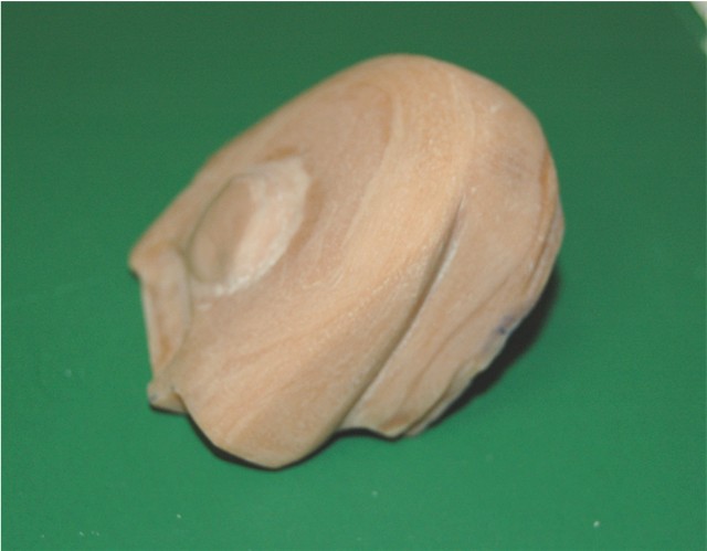 Its still hard to see all the contours, but they are there. I need to do some
final detail work on it to be completely satisfied.
Its still hard to see all the contours, but they are there. I need to do some
final detail work on it to be completely satisfied.
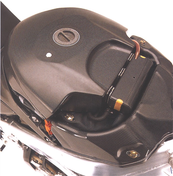 This is what I want it to eventually look like.
:)
This is what I want it to eventually look like.
:)
I have the air-box pieces I cut off, set aside so I can glue them back together and reshape them to fit and then work on the bottom half of the air-box as well. These were all parts I wanted to make out of carbon fiber cloth, but the weave is too big, so I'm afraid it will be resin, covered with carbon decals.
I did carry out a little experiment with Carbon
fiber cloth and made another Tank cover, using the same mold I had made the
resin one in. Only this time, once I lined it with layers of resin soaked
Carbon fiber cloth, I placed a balloon filled with water inside it and pulled
a vacuum (with my food saver) This is the result after 3 attempts
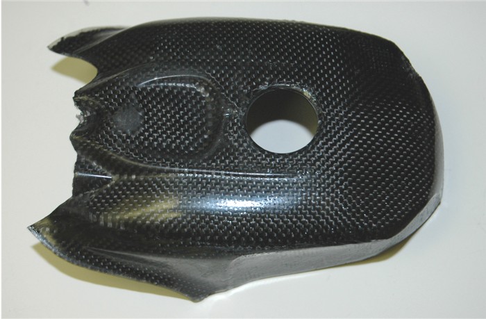
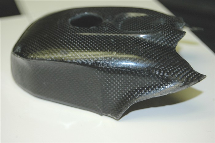
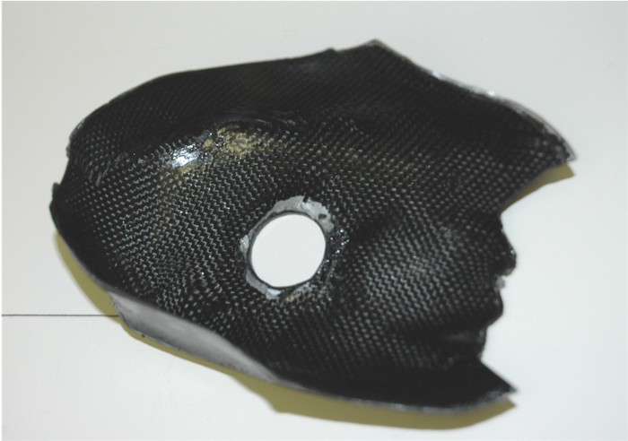 Don't know if I'll use it yet. ;)
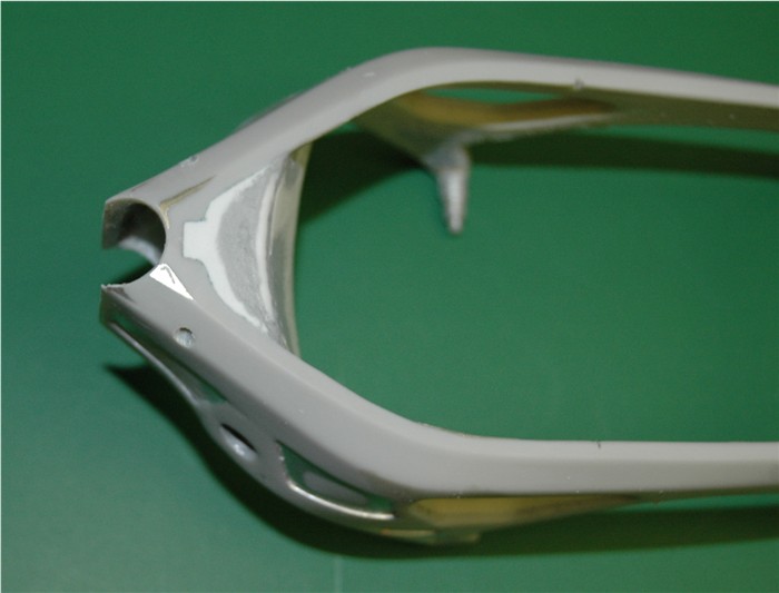
Back to the frame: The sheet work has been
finished off at the steering head and adjustments made on the frame there.
 and filled the lower rear bracket
 A little more work with filler and sanding the frame, its getting closer
 I have done some tests on reproducing weld lines,
because I am very unhappy with the ones on the kit. So I have removed all
unwanted weld lines,
I have done some tests on reproducing weld lines,
because I am very unhappy with the ones on the kit. So I have removed all
unwanted weld lines,
 brackets and steering head. Filled in holes that will be redone correctly.
Before I put new weld lines I will add all the new brackets, drill the new
holes and install the steering head.
brackets and steering head. Filled in holes that will be redone correctly.
Before I put new weld lines I will add all the new brackets, drill the new
holes and install the steering head.
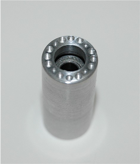
I machined a new steering head, which has 6
parts. The main body with an 8mm reamed hole all the way through it, two end
caps with a piece of stainless 5/16" OD tube. (No reason for it being
stainless, it is just what I had laying around.) I super glued one cap on
the bottom
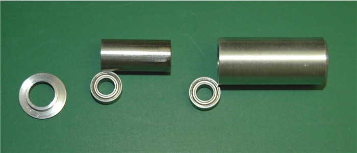 end of the body, dropped in one bearing, slid the tube in with the second
bearing on top of that, finally super gluing the top in place.
end of the body, dropped in one bearing, slid the tube in with the second
bearing on top of that, finally super gluing the top in place.
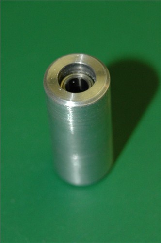 This holds the outer part of the bearing nice and solidly. The steering "axle"
for want of a better word (or the correct one) will be a nice "push
fit" on the inside of the bearings. It will also have all the working
adjustments, top and bottom. There is a little machining to do on the top of
the head, which I will do before installing it.
This holds the outer part of the bearing nice and solidly. The steering "axle"
for want of a better word (or the correct one) will be a nice "push
fit" on the inside of the bearings. It will also have all the working
adjustments, top and bottom. There is a little machining to do on the top of
the head, which I will do before installing it.
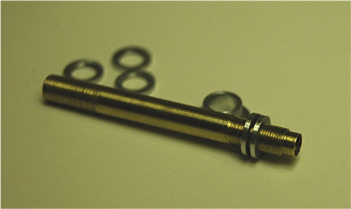
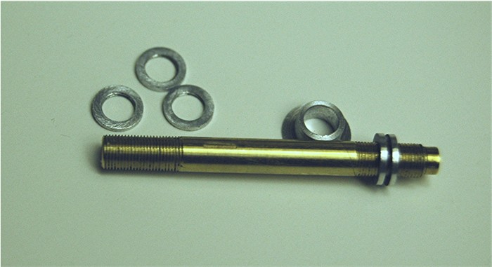
I machined the spindle, bushes and round nuts,
this evening, for the steering head. The spindle is machined to 4mm OD, a
perfect fit inside the bearings
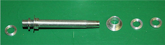 and perfect for a 4mm x 0.35 pitch thread on each end. The bushes with the
flanges fit in the top and bottom of the steering head and clamp against the
inner part of the bearings, when the round, notched nuts are installed. There
are two at each end to lock against each other. The left end in the picture is
the top, with a relief machined at the end to fit in the bottom of the top
triple clamp. I'm not too happy with the thread on that end so I may make
another, The top end is also threaded on the inside with a 4-48 UNF
thread to allow the top triple clamp to be attached firmly to the spindle with
another bolt.
and perfect for a 4mm x 0.35 pitch thread on each end. The bushes with the
flanges fit in the top and bottom of the steering head and clamp against the
inner part of the bearings, when the round, notched nuts are installed. There
are two at each end to lock against each other. The left end in the picture is
the top, with a relief machined at the end to fit in the bottom of the top
triple clamp. I'm not too happy with the thread on that end so I may make
another, The top end is also threaded on the inside with a 4-48 UNF
thread to allow the top triple clamp to be attached firmly to the spindle with
another bolt.
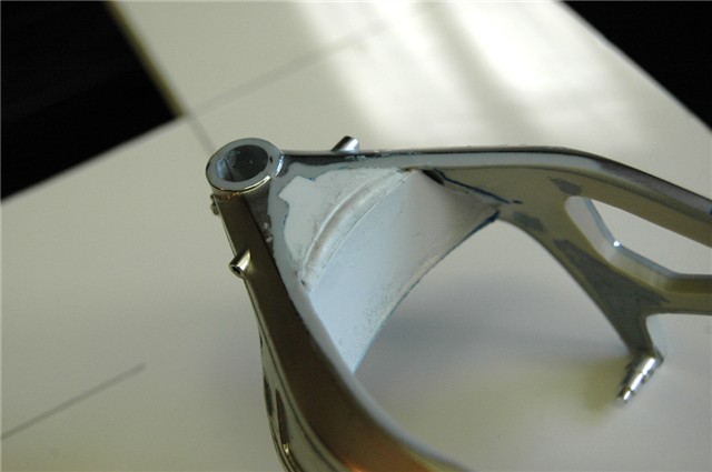
When its assembled in the steering head and in the frame you get a better idea
of how it looks
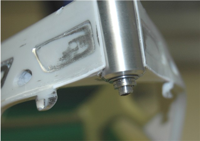
Assembled it looks better than in parts. It is all about
adjustment.............you can adjust the angle of the steering and maintain
the same overall fork length by raising or lowering the steering spindle by
adjusting the round lock nuts up and down. Super detail, all about realism. ;)
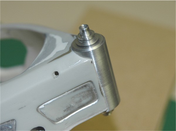
As I said, I went ahead and made a new steering
spindle out of brass this time and threaded the inside with a 3mm thread this
time. It is fractionally finer thread.
 much improved
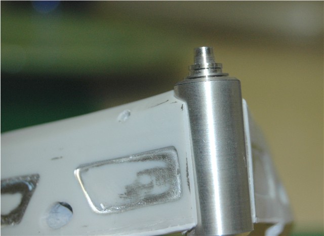
 I also took the time to finish off the steering head with some extra detail.
 I had to machine a new top as it was a little incorrect. It was not supposed
to have a beveled edge, and I also needed to drill the holes in the top.
I had to machine a new top as it was a little incorrect. It was not supposed
to have a beveled edge, and I also needed to drill the holes in the top.
Some new equipment arrived I had ordered and I wanted to check it out. The holes in the top of the steering head were the first test of the new Rotary table. It worked so well I decided to try it out on the rear sprocket.
Its funny, I have been trying
to find out what size the chains are used on the MotoGP bikes, for a couple of
years. I eventually followed the link of one of the sponsors, who supply the
chains. When I finally get it sorted out, I look at one of my reference
photos, and low-and-behold "Stamped" on one link is "520"! It had been staring
me in the face all this time. :)
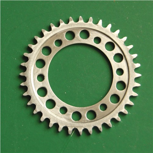
That is a complete job to itself. Machining a blank on
the lathe and then drilling all the holes in it for mounting and what will be
the teeth.
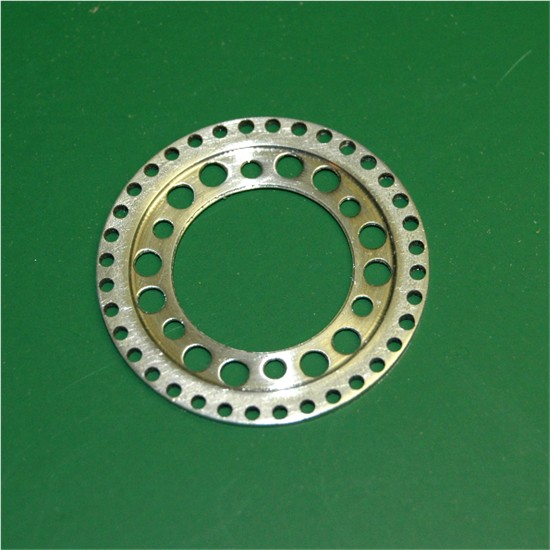
 I am really happy with it at this stage. I now have to make a jig to machine
the teeth. Well a few lucky finds in "Rocklers" and the use of some scraps I
have laying around, this is how the jig started out.
I am really happy with it at this stage. I now have to make a jig to machine
the teeth. Well a few lucky finds in "Rocklers" and the use of some scraps I
have laying around, this is how the jig started out.
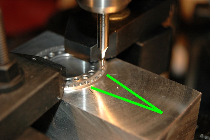 The two green lines point to the holes I will use for locating pins, while I
machine the teeth on it. They are 1/16" diameter holes all around the edge.
The two green lines point to the holes I will use for locating pins, while I
machine the teeth on it. They are 1/16" diameter holes all around the edge.
This is the first set-up
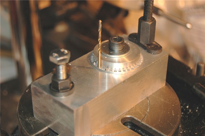 The hole with the drill bit in, is crucial. That hole has to be perfectly in
line and centered with the spindle of the drill press and the center of the
rotary table. I realized at this point I would have to machine a bevel on the
top edge of the clamping washer to allow the Mill bit the correct amount of
travel. First cuts done, looking good.
The hole with the drill bit in, is crucial. That hole has to be perfectly in
line and centered with the spindle of the drill press and the center of the
rotary table. I realized at this point I would have to machine a bevel on the
top edge of the clamping washer to allow the Mill bit the correct amount of
travel. First cuts done, looking good.
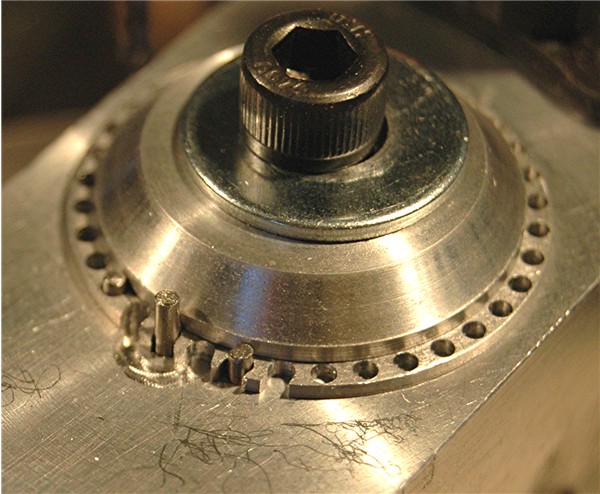
 About 1/3 of them cut, its not looking too bad. I had to make some very minor
adjustments as I went along? Not sure why.
About 1/3 of them cut, its not looking too bad. I had to make some very minor
adjustments as I went along? Not sure why.
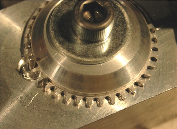
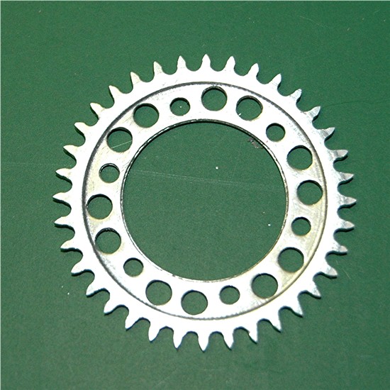
 Finished. Not bad, but I'm not happy with it
 I have machined the bevel on the edge of the teeth as well. I then realized what
the problem was and why I had to make the adjustments. I had designed/drawn it to actual scale, so the chains
rollers would be 0.066" diameter, however, I was using a mill bit that is only
0.0625" in diameter. So to make it correct, the pitch diameter of the sprocket
needed to be 0.020" smaller in diameter. So I have to modify the jig to
remake it. :( Oh well! .....................................
I have machined the bevel on the edge of the teeth as well. I then realized what
the problem was and why I had to make the adjustments. I had designed/drawn it to actual scale, so the chains
rollers would be 0.066" diameter, however, I was using a mill bit that is only
0.0625" in diameter. So to make it correct, the pitch diameter of the sprocket
needed to be 0.020" smaller in diameter. So I have to modify the jig to
remake it. :( Oh well! .....................................
Modified the jig
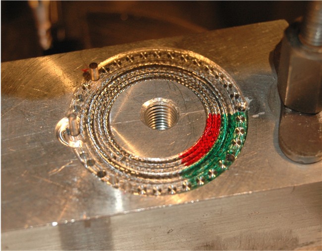 It is now how I originally designed it. There are two recessed circles, which
are hard to see so I have marked them in red and green marker pen so you can
see them more easily. The center section fits the inside diameter of the
sprocket perfectly.
It is now how I originally designed it. There are two recessed circles, which
are hard to see so I have marked them in red and green marker pen so you can
see them more easily. The center section fits the inside diameter of the
sprocket perfectly.
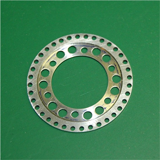
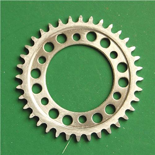
So with the pitch diameter adjustment made, I ran around the sprocket again,
no one single adjustment this time. :) But when I removed the sprocket it
looked worse than it did before, because it was slightly off. No big deal
though. This is what happens when scratch building, just not many people will
tell you that they screwed up. ;)
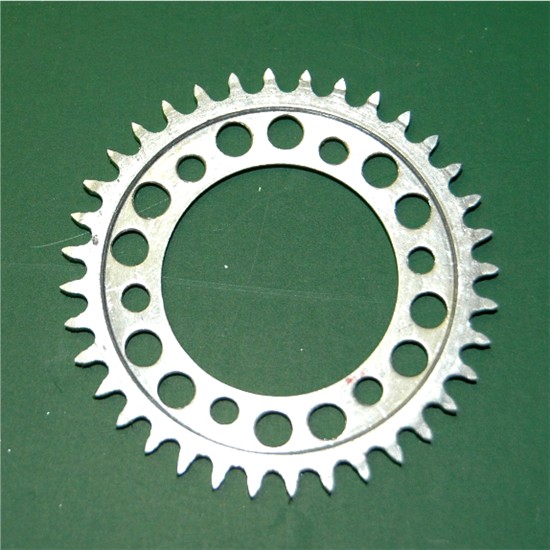 You can see one side of each tooth is "just not right".
4/20/09
I have been away from this project for a while. I have been teaching myself to
use a 3D software "Solid Works" and along with a few other things have not had
time to do anything. However, in the last couple of weeks of using the
software, I returned to the fork leg bottom.
As I had to draw it anyway so I could make the
parts, I decided to draw them in Solid works, after a few attempts this is
what I finished up with.
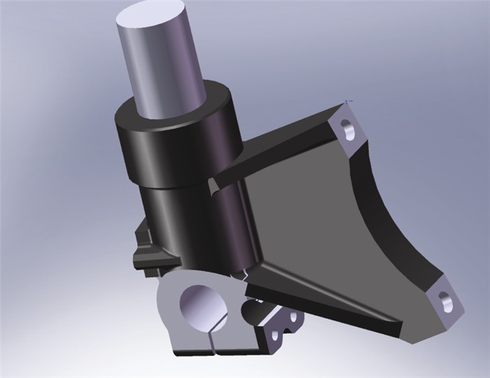 I was very happy with it and have done a lot more on the front end with the
software. (I also have been working on parts for
the Lotus 72C). In that vein, I wanted
to find out how parts would turn out from a 3D printer. But I don't have one.
I contacted a local distributor of 3D printers (Their
cheapest is $19,000.00) but it will
print in 0.0035" layers, most others will only print in 0.010" layers, and
they cost a lot more.
I was very happy with it and have done a lot more on the front end with the
software. (I also have been working on parts for
the Lotus 72C). In that vein, I wanted
to find out how parts would turn out from a 3D printer. But I don't have one.
I contacted a local distributor of 3D printers (Their
cheapest is $19,000.00) but it will
print in 0.0035" layers, most others will only print in 0.010" layers, and
they cost a lot more.
The nice part is, I emailed the company two files
from the Solid Works program on Friday afternoon, and the company said they
would print them over the weekend.
............................................................I picked them up
today. :)
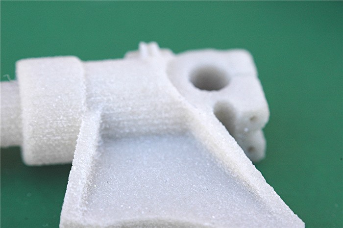
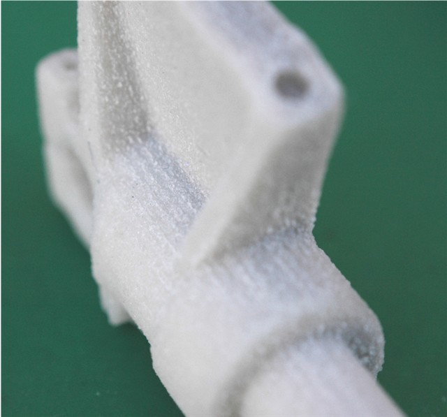
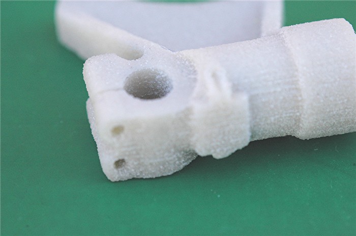 Now remember the overall length of this is approx. 1" and those lines are the
layers at 0.0035". That is exactly as it comes out of the printer, with the
dust blown off. Unfortunately, although I removed the thread from the drawing
before sending it, I left the hole, instead of a dimple, on the mounting bush,
which meant the material was too thin at that point and whoever blew the dust
off used too much pressure, but no big deal. I am actually very happy with the
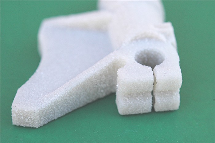
way they turned out. I will have to clean them up now. Here are more images
before I do that.
Now remember the overall length of this is approx. 1" and those lines are the
layers at 0.0035". That is exactly as it comes out of the printer, with the
dust blown off. Unfortunately, although I removed the thread from the drawing
before sending it, I left the hole, instead of a dimple, on the mounting bush,
which meant the material was too thin at that point and whoever blew the dust
off used too much pressure, but no big deal. I am actually very happy with the
way they turned out. I will have to clean them up now. Here are more images
before I do that.
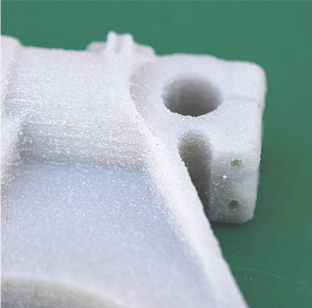
 The two holes in the first picture are 1mm dia. and that gap is 0.15mm if I
remember correctly. It looks very crystalline, which will disappear when I
clean them up. Surprisingly the crystals are quite hard and will need to be
sanded off.
The two holes in the first picture are 1mm dia. and that gap is 0.15mm if I
remember correctly. It looks very crystalline, which will disappear when I
clean them up. Surprisingly the crystals are quite hard and will need to be
sanded off.